
In this article, you’ll see how to build a Simulink model from a MATLAB script. (You can find the complete script at the end of the article.) More specifically, you’ll learn to:
- Open a Simulink model from a MATLAB script
- Add a block to your model
- Create a subsystem from MATLAB
- Add/remove lines and delete blocks
- Modify the position of a block
- Save and simulate the model from MATLAB
Open a Simulink Model from a MATLAB Script
First, click on “New Script” on the top left of MATLAB. This will create a new script by opening the MATLAB editor. Let’s start by saving that script and calling it “buildModel.m”.
- Name your model: first, decide on the name of the model. For this example, let’s name it mySimpleModel. We can define a variable named modelName that will have the value “mySimpleModel:”
modelName = 'mySimpleModel'; - Create and open your model: to create a new model use the MATLAB command new_system. This will create the model in Simulink and output the handle of the model. You will want to open that new model so that you can add blocks inside by using the MATLAB command open_system.
% create and open the new model
open_system(new_system(modelName));
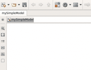
Try running the script. Congratulations! You’ve successfully created your first model programmatically:
Add a Block to Your Model
- Define fixed variables: let’s start by defining the variables “offset” (which will determine the space between two blocks) and “hSubsystems” (which we will use in the later sections):
offset = 100; % horizontal space between 2 blocks
hSubsystems = 60; % height of your subsystems
- Add a block: now, let’s add a sinewave to your model. The first question to ask if you want to add a block is where to position it.
- Define the position: first, keep in mind the (0, 0) coordinate of the model is at the top left corner. Here’s how to define the position of your block:
% sinewave position
xSW = 30; % horizontal offset of your sinewave block
ySW = 30; % vertical offset of your sinewave block
wSW = 30; % width of your sinewave block
hSW = 30; % height of your sinewave block
posSW= [xSW ySW xSW+wSW ySW+hSW];
- Use add_block: deploy the add_block MATLAB function to add a block to the model. We will do this in the following way:
add_block(simulinkLibraryBlockLocation, blockDestination, 'Position', postion)
Applied to our example, we get
% add the Sine Wave from Simulink library
blockName = 'Sine Wave'; % name of the block as it is named in the Simulink library
add_block(['simulink/Sources/' blockName], [modelName '/' blockName], 'Position', posSW);
So, the first argument is the location of the block in the Simulink library. The second argument is where we want to add the block, namely in the model that we are trying to build. Finally, the third and fourth arguments set the position of the block.
- Define the position: first, keep in mind the (0, 0) coordinate of the model is at the top left corner. Here’s how to define the position of your block:
Create A Subsystem from MATLAB
- Create Inport/Outport: now that we have a sinewave and we know how to add blocks, let’s add an input and an output to our model:
% add I/O
add_block('simulink/Sources/In1', [modelName '/In1']);
add_block('simulink/Sinks/Out1', [modelName '/Out1']);
- Add a Subsystem: let’s add a subsystem containing the inport and outport that we just created. The reason why we’ve added an inport and outport before creating the subsystem is because this way the inport and outport will be created inside the subsystem and outside of it (at the top level of your model).
- Get the port handles: to include those ports inside the subsystem, we need to reference them when we create the subsystem. To do that, we need the handle of the inport and of the outport, which we get as follows:
inputPort = get_param([modelName '/In1'], 'handle');
outputPort = get_param([modelName '/Out1'], 'handle');
- Create the Subsystem: at this point, we can create the subsystem by using an array of the handles of the inport and the outport as follows:
subSystemContent = [inputPort outputPort];
Simulink.BlockDiagram.createSubSystem(subSystemContent);
- Get the port handles: to include those ports inside the subsystem, we need to reference them when we create the subsystem. To do that, we need the handle of the inport and of the outport, which we get as follows:
Add/Remove Lines And Delete Blocks
- delete lines: we actually don’t need the inport and outport at the top level of the model because we will use the sinewave and the scope instead. So, let’s first delete the lines that connect the inport and the outport to the subsystems:
delete_line(modelName,'In1/1','Subsystem/1');
delete_line(modelName,'Subsystem/1','Out1/1');
- delete blocks: we can then delete the inport and outport by using the delete_block MATLAB command :
delete_block([modelName '/In1']);
delete_block([modelName '/Out1']);
- Connect blocks: however, we want the sinewave to be connected to the subsystem in which we will add some blocks. To do so, we can use the add_line MATLAB command:
% add line between the Input and Output ports
add_line(modelName, 'Sine Wave/1', 'Subsystem/1', 'autorouting', 'on');
- modelName: name of the model
- Sine Wave/1: location of the source of the line (Here we only have one output for the sinewave, so the source is sinewave/1. For a block that has several outputs, you could have a number other than one, depending on the output that the line is connected to.)
- Subsystem/1: destination of the line
- autorouting: option of the add_line command
- on: set the ‘autorouting’ option to ‘on’
Modify the Position of a Block
- Subsystem position: let’s modify the position of the subsystem so that it doesn’t overlap other blocks:
% position Subsystem
wSubsystem = 8;
posSubsystem = posSW;
posSubsystem(1) = posSubsystem(1)+offset;
posSubsystem(2) = posSW(2)-(hSubsystems-hSW)/2;
posSubsystem(3) = posSubsystem(3)+offset+wSubsystem;
posSubsystem(4) = posSubsystem(2)+hSubsystems;
set_param([modelName '/Subsystem'],'Position', posSubsystem);
To do so, you need to define the position as you did before for the sinewave. The only difference is that you now have to use the MATLAB command set_param:
-
- [modelName ‘/Subsystem’]: location of the block that you want to modify
- ‘Position’: option of the set_param command
- posSubsystem: vector of the desired position
-
- Inport position: you can then modify the position of the inport as well inside the subsystem:
% position inport
pathInport = [modelName '/Subsystem/In1'];
currentPos = get_param(pathInport, 'Position');
currentHeight = currentPos(4) - currentPos(2);
currentWidth = currentPos(3) - currentPos(1);
posInport(1) = posSW(1);
posInport(2) = posSW(2);
posInport(3) = posInport(1)+currentWidth;
posInport(4) = posInport(2)+currentHeight;
set_param(pathInport,'Position', posInport);
At this point, we want to keep the height and width of the inport, so we need to get the current position of the inport. We do this by using the MATLAB command get_param and referencing the name of the port.
Build the Model
You now know everything you need about building a model from MATLAB, so let’s actually build it inside the subsystem.
- Add logic in the Subsystem: So let’s do a simple calculation which is taking the first input and adding it the value 1:
\( Out = In + 1 \)
Using what we’ve seen in the previous section, this is how to do that:
% add the Add block from Simulink library
blockName = 'Add';
pathAdd = [modelName '/Subsystem/' blockName];
add_block(['simulink/Math Operations/' blockName], pathAdd);
currentPos = get_param(pathAdd, 'Position');
currentHeight = currentPos(4) - currentPos(2);
currentWidth= currentPos(3) - currentPos(1);
posAdd(1) = posInport(1) + offset;
posAdd(2) = posInport(2)-1;
posAdd(3) = posAdd(1)+currentWidth;
posAdd(4) = posAdd(2)+currentHeight;
set_param(pathAdd,'Position', posAdd);

% add line between the Input and Output ports
add_line([modelName '/Subsystem'], 'In1/1', 'Add/1', 'autorouting', 'on');

blockName = 'Constant';
pathConstant = [modelName '/Subsystem/' blockName];
add_block(['simulink/Sources/' blockName], pathConstant);
currentPos = get_param(pathConstant, 'Position');
currentHeight = currentPos(4) - currentPos(2);
currentWidth = currentPos(3) - currentPos(1);
posConstant(1) = posSW(1);
posConstant(2) = posSW(2)+offset/2;
posConstant(3) = posConstant(1)+currentWidth;
posConstant(4) = posConstant(2)+currentHeight;
set_param(pathConstant,'Position', posConstant);

% add line between the Input and Output ports
add_line([modelName '/Subsystem'], [blockName '/1'], 'Add/2', 'autorouting', 'on');

% position outport
blockName = 'Out1';
pathOutport = [modelName '/Subsystem/' blockName];
currentPos = get_param(pathOutport, 'Position');
currentHeight = currentPos(4) - currentPos(2);
currentWidth = currentPos(3) - currentPos(1);
posOutport(1) = posAdd(1) + offset;
posOutport(2) = posInport(2) + (posAdd(4) - posAdd(2))/2 - currentHeight/2;
posOutport(3) = posOutport(1)+currentWidth;
posOutport(4) = posOutport(2)+currentHeight;
set_param(pathOutport,'Position', posOutport);

% add line between the Input and Output ports
add_line([modelName '/Subsystem'], 'Add/1', [blockName '/1'], 'autorouting', 'on');
- Add a scope: then, we just need to add a scope at the top level and link it to the output of the subsystem so that we can observe it:
blockName = 'Scope';
pathScope = [modelName '/' blockName];
add_block(['simulink/Sinks/' blockName], pathScope);
currentPos = get_param(pathScope, 'Position');
currentHeight = currentPos(4) - currentPos(2);
currentWidth = currentPos(3) - currentPos(1);
posScope(1) = posSubsystem(1) + offset;
posScope(2) = posSubsystem(2) + (posSubsystem(4) - posSubsystem(2))/2 - currentHeight/2;
posScope(3) = posScope(1)+currentWidth;
posScope(4) = posScope(2)+currentHeight;
set_param(pathScope,'Position', posScope);

% add line between the Input and Output ports
add_line(modelName, 'Subsystem/1', [blockName '/1'], 'autorouting', 'on');
Saving and Simulating the Model from MATLAB
- Save your model: you can save your model using the MATLAB command save_system followed by the name of your model:
save_system(modelName)
- Simulate your model: you can simulate this model using the sim MATLAB command:
sim(modelName)
Finally, if you double-click on the scope this is what you will get:
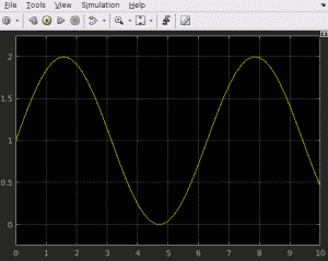
As you can see, this is a sinewave that has an average value of 1 because we’ve added 1 to the sinewave inside the subsystem.
Key takeaways:
- Create a model using the MATLAB command:
open_system(new_system(modelName));
- Add a block using the add_block MATLAB command:
add_block(simulinkLibraryBlockLocation, blockDestination, 'Position', postion)
- Create a subsystem by referencing the blocks you want your subsystem to contain with their handles [which you can get using the MATLAB command get_param(block, ‘handle’)] and by using the following MATLAB command:
Simulink.BlockDiagram.createSubSystem(subSystemContent);
- Connect blocks using the add_line MATLAB command:
add_line(modelName, sourceBlock, destinationBlock, 'autorouting', 'on');
- Modify the position using the MATLAB command:
set_param(block, position, positionValue);
- Save and simulate your model using:
save_system(model) % save the model
sim(model) % simulate the model
Here’s the complete script:
modelName = 'mySimpleModel';

% create and open the test model
open_system(new_system(modelName));

offset = 100;
hSubsystems = 60;

% position sinewave
xSW= 30;
ySW = 30;
wSW = 30;
hSW = 30;
posSW= [xSW ySW xSW+wSW ySW+hSW];

% add the Sine Wave from Simulink library
blockName = 'Sine Wave';
add_block(['simulink/Sources/' blockName], [modelName '/' blockName], 'Position', posSW);

% create a subsytem with I/O
add_block('simulink/Sources/In1', [modelName '/In1']);
add_block('simulink/Sinks/Out1', [modelName '/Out1']);
inputPort = get_param([modelName '/In1'], 'handle');
outputPort = get_param([modelName '/Out1'], 'handle');
subSystemContent = [inputPort outputPort];
Simulink.BlockDiagram.createSubSystem(subSystemContent);

% delete the I/O created in modelName
delete_line(modelName,'In1/1','Subsystem/1');
delete_line(modelName,'Subsystem/1','Out1/1');
delete_block([modelName '/In1']);
delete_block([modelName '/Out1']);

% add line between the Input and Output ports
add_line(modelName, 'Sine Wave/1', 'Subsystem/1', 'autorouting', 'on');

% position Subsystem
wSubsystem = 8;
posSubsystem = posSW;
posSubsystem(1) = posSubsystem(1)+offset;
posSubsystem(2) = posSW(2)-(hSubsystems-hSW)/2;
posSubsystem(3) = posSubsystem(3)+offset+wSubsystem;
posSubsystem(4) = posSubsystem(2)+hSubsystems;
set_param([modelName '/Subsystem'],'Position', posSubsystem);

% position inport
pathInport = [modelName '/Subsystem/In1'];
currentPos = get_param(pathInport, 'Position');
currentHeight = currentPos(4) - currentPos(2);
currentWidth = currentPos(3) - currentPos(1);
posInport(1) = posSW(1);
posInport(2) = posSW(2);
posInport(3) = posInport(1)+currentWidth;
posInport(4) = posInport(2)+currentHeight;
set_param(pathInport,'Position', posInport);

% add the Add block from Simulink library
blockName = 'Add';
pathAdd = [modelName '/Subsystem/' blockName];
add_block(['simulink/Math Operations/' blockName], pathAdd);
currentPos = get_param(pathAdd, 'Position');
currentHeight = currentPos(4) - currentPos(2);
currentWidth= currentPos(3) - currentPos(1);
posAdd(1) = posInport(1) + offset;
posAdd(2) = posInport(2)-1;
posAdd(3) = posAdd(1)+currentWidth;
posAdd(4) = posAdd(2)+currentHeight;
set_param(pathAdd,'Position', posAdd);

% add line between the Input and Output ports
add_line([modelName '/Subsystem'], 'In1/1', 'Add/1', 'autorouting', 'on');

blockName = 'Constant';
pathConstant = [modelName '/Subsystem/' blockName];
add_block(['simulink/Sources/' blockName], pathConstant);
currentPos = get_param(pathConstant, 'Position');
currentHeight = currentPos(4) - currentPos(2);
currentWidth = currentPos(3) - currentPos(1);
posConstant(1) = posSW(1);
posConstant(2) = posSW(2)+offset/2;
posConstant(3) = posConstant(1)+currentWidth;
posConstant(4) = posConstant(2)+currentHeight;
set_param(pathConstant,'Position', posConstant);

% add line between the Input and Output ports
add_line([modelName '/Subsystem'], [blockName '/1'], 'Add/2', 'autorouting', 'on');

% position outport
blockName = 'Out1';
pathOutport = [modelName '/Subsystem/' blockName];
currentPos = get_param(pathOutport, 'Position');
currentHeight = currentPos(4) - currentPos(2);
currentWidth = currentPos(3) - currentPos(1);
posOutport(1) = posAdd(1) + offset;
posOutport(2) = posInport(2) + (posAdd(4) - posAdd(2))/2 - currentHeight/2;
posOutport(3) = posOutport(1)+currentWidth;
posOutport(4) = posOutport(2)+currentHeight;
set_param(pathOutport,'Position', posOutport);

% add line between the Input and Output ports
add_line([modelName '/Subsystem'], 'Add/1', [blockName '/1'], 'autorouting', 'on');


blockName = 'Scope';
pathScope = [modelName '/' blockName];
add_block(['simulink/Sinks/' blockName], pathScope);
currentPos = get_param(pathScope, 'Position');
currentHeight = currentPos(4) - currentPos(2);
currentWidth = currentPos(3) - currentPos(1);
posScope(1) = posSubsystem(1) + offset;
posScope(2) = posSubsystem(2) + (posSubsystem(4) - posSubsystem(2))/2 - currentHeight/2;
posScope(3) = posScope(1)+currentWidth;
posScope(4) = posScope(2)+currentHeight;
set_param(pathScope,'Position', posScope);

% add line between the Input and Output ports
add_line(modelName, 'Subsystem/1', [blockName '/1'], 'autorouting', 'on');

save_system(modelName)
sim(modelName)
On the same topic, the following MathWorks documentation can be very helpful: Programmatic Modeling Basics.