
In this article, you’ll learn how to use the Mux block to create Simulink vectors as well as how to use the other Simulink blocks needed to manipulate them. More specifically, you’ll learn to:
- Create a vector in Simulink using a Mux block
- Observe a vector using a Simulink scope
- Split a vector using a Demux block
- Extract a signal from a vector using a Selector block
Simulink Mux: Create a Vector in Simulink
In order to create Simulink vectors, you have to create at least two signals from which you can create a Simulink vector. Let’s try creating a Simulink model that we will name “vectorExample.slx.” To do that, follow these steps:
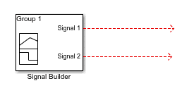
- Add a signal builder: Let’s add a Simulink signal builder to this model so that we can create two signals:

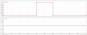
- Add a signal to the signal builder: a “pulse signal” for signal 1 and a “constant signal” for signal 2. The two signals look like this:If you want to learn how to create two signals from a signal builder, see this signal builder tutorial.
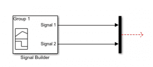
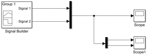
- Create a vector using the Mux block: now that we have a signal builder in our Simulink model, we can create a vector from those two signals by finding the Mux block, located in the Simulink library in “Simulink/Signal Routing.” If you double-click on the Mux block, you can select the number of inputs (2 by default). To create a vector, you simply have to connect those two signals to the mux block as follows:Congratulations, you have now created your first vector in Simulink. Next, let’s see how to observe that vector throughout time.
Observe a Vector in the Simulink Scope
In order to do this, simply add a scope to your model and connect it to the mux block:
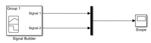
Then, run your model and double-click on the scope, you should have the following:
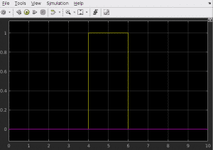
As you can see both signals are on the same scope but with different colors.
- Simulink scope color order: You can know what vector is in your scope by using the following color code:
- yellow -> Signal 1
- magenta -> Signal 2
- cyan
- red
- green
- dark blue
- yellow -> Signal 1
- Interpretation: Signal 1 is in yellow, Signal 2 is in magenta, etc. (In a Simulink vector, the first signal is the one at the top of the Mux block.)
This is the easiest way to observe a vector. However, you can also split the vector to observe every element separately in a scope, as we will see in the next section.
Demux Simulink Block: Splitting a Vector
If you want to split the vector that you created into every single element, you can use the Demux block:
- You can find it in the Simulink library “Simulink/Signal Routing.”
- To use the Demux block, simply connect the vector to the vector to the input and the output to a Scope to visualize the signals:
- You can use two scopes to look at every signal separately or add an input to the scope in order to see both signals in the same scope. To do that, you can double-click on the scope and go to File > Number of Input Ports > 2. This will add an input port to your scope. Then, connect those signals to your scope. Now, if run the simulation again, you’ll see that you have the same results as the first one.
Let’s say you only want to visualize the second signal element from your vector: how do you select this signal specifically and visualize it without having to use a Demux block and output every single element of your vector? (In our example, it is fine to output every element because we only have 2, but keep in mind that in a real-life example you could have lots of signals in a vector, and it would take a significant amount of time if you use a Demux block.)
The answer is to use a selector block.
Using A Selector Block in Simulink
Let’s use a selector block to visualize the second element of our Simulink vector only.
- Add a Selector block: You can find the selector block in the Simulink library “Simulink/Signal Routing.” Let’s add this to our model and double-click on it to see how it works:
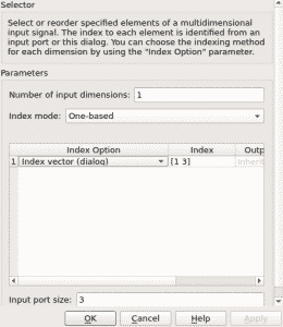
- Index: First, let’s have a look at the index field, which represents the element(s) that we want to select. In this example, the elements are the first and the third element of the input signal vector. Since we only want the second element of our input vector, we can just replace this vector by the vector containing only the element 2: [2].
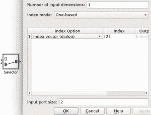
- Input port size: Now, we’ve selected the second element of the input vector. However, as you can see the input port size is 3. Because our input signal vector has only two elements, we can just replace the input port size by 2. This is what the selector should look like:
If you connect this selector to a scope and run the simulation, you get the following :
This is the second element of our input vector, which is what we wanted to observe.
Key takeaways:
- You can create a vector by using the Mux Simulink block:
- The Mux block is located in the Simulink library “Simulink/Signal Routing.”
- Add an input signal to the Mux block by double-clicking on it and using the “Number of inputs” box.
- Connect a vector to a scope and observe it using the following color code:
- yellow
- magenta
- cyan
- red
- green
- dark blue
The first signal is in yellow, the second is in magenta, etc.
- yellow
- You can output every element of a vector using a Demux block:
- The Demux block is located in the Simulink library “Simulink/Signal Routing.“
- Add an output signal to the Demux block by double-clicking on it and using the “Number of outputs” box.
- Find and extract a specific signal by using the selector block and setting the index to the element(s) that you want to output and the input port size to the size of your input vector.
If you want more information about mux signals, see the following MathWorks documentation: https://www.mathworks.com/help/simulink/ug/virtual-signals.html#brp5v4k-1